ADU Closet Prep
Five jobs in the small closet under the stairs in the ADU: take the shelves out on the left, take the top three shelves out of the back bay, take the two low-voltage faceplates off the wall, patch and paint the walls, build a solid wood backer on the back wall so a cable box can be screwed into the studs. The fan and air intake on the left wall come later, from the AC crew. The shelf boards get reused for the backer. Nothing electrical, nothing structural.
Thursday, October 1: the handyman and the electrician are both here. Order of the day:
- Before anyone starts: Bill clears the network gear off the third shelf in the back bay and agrees the power-off time with the electrician (the house internet is down while that outlet is off).
- Handyman, first thing: the top three shelves out of the back bay (step 2), so the electrician can reach both the back wall and the right side wall.
- Then side by side. Electrician: moves the outlet onto the bay's right side wall and retires the old box (details). Handyman, meanwhile, stays out of the back bay: left wall shelves out (step 1), faceplates off (step 3, once the electrician says the bay is clear), and prep of the left wall.
- After the electrician is done and power is back: handyman finds the framing, patches and paints (including the electrician's holes), then backer, bracket and ducts. The backer can go on as soon as the patch under it has set; it doesn't need to wait for paint.
The closet
It's the closet under the stairs. Walk in the door: a long wall of shelves is on your left under the sloped ceiling, a blank wall is on your right, and straight ahead is a narrow bay about 22 inches wide with shelves holding boxes and the network gear. The wall plates where the cables come through the wall are in that back bay.
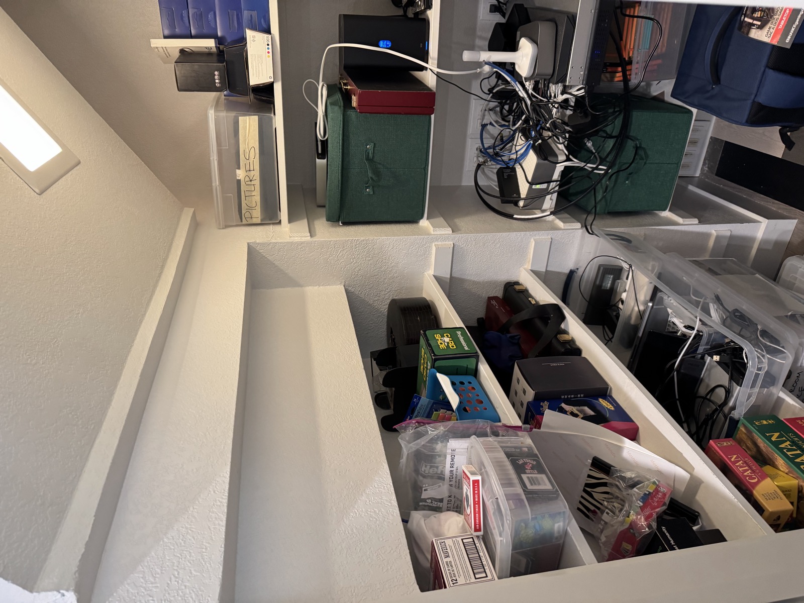
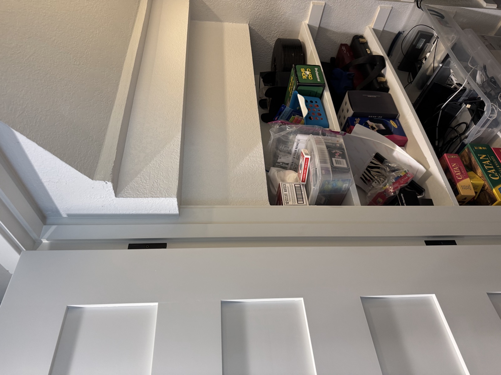
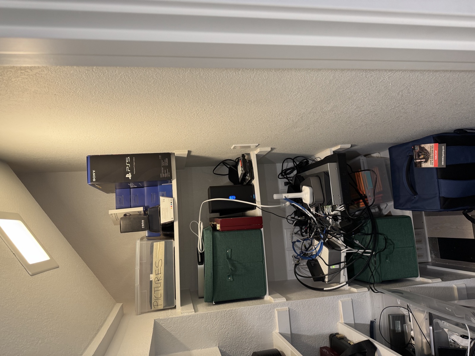
Two things not to touch. (1) The black boxes with the cables in the back bay, and every cable plugged into them: that is the house's internet and cameras. Don't unplug, don't move, don't tug. If that shelf still has gear on it when you arrive, stop and call Bill. (2) The cables coming out of the wall in the back bay: never cut, never pull, never unplug. They are data lines that run all over the property. Taking the faceplates off the wall (step 3) is fine; the cables behind them are not to be disturbed.
The work, in order
Left wall: all the shelves come out
Empty every shelf on the left wall (Photo 2) and stack the contents outside the closet. Remove the shelf boards, then the wood cleats or brackets they rest on, down to bare drywall. Pull or back out every screw and nail. The holes and cleat marks get patched and painted in step 5.
Keep the shelf boards. They become the backer in step 6. Set the two longest, flattest ones aside; the rest can go.
Back bay: the top three shelves come out
In the narrow bay at the back (Photo 3), remove the top three shelves and their cleats: the "Pictures" shelf, the green-box shelf, and the network-gear shelf. Bill will have moved the gear off that third shelf first. Anything below the third shelf stays as it is unless Bill says otherwise.
Work around the wall plates and the cables coming out of them. Don't cover them with anything and don't let a shelf board catch a cable on the way out.
Take the two low-voltage faceplates off
Before a single cable comes off its jack, label it. Each cable gets a wrap-around label (Avery labels on site) with the plate and position it came from, e.g.
Plate L · jack 3, and any writing already on the jack or the cable. Take a clear photo of each plate's back before unplugging anything and text them to Bill. On the left side of the back bay's wall there are two two-gang low-voltage faceplates (the flat plates the network cables come through, no outlets in them). Unscrew both and set the plates and screws aside for Bill. Leave the cables exactly where they are, hanging out of the wall; the plastic ring or bracket behind each plate can stay. Don't push the cables back into the wall and don't pull any slack out.The nearby power outlets stay as they are: cover plates on, nothing touched.
Find the framing in the back bay
Run a stud finder across the back wall of the bay, from side to side, at about waist height. The bay is only 22 inches wide, so expect one stud somewhere in the middle plus solid framing in both corners. Mark every stud edge in pencil, top to bottom, so the marks are still visible after the backer goes on. Stay at least 2 inches away from the cable openings and the power outlets when you screw into this wall: the cables run inside it right there.
Patch and paint
Once the shelves and cleats are off, the left wall and the upper back bay have screw holes, cleat marks and bare patches. Make them look like a finished wall before anything new goes up.
- Cover the network gear first. Drape a plastic sheet or drop cloth over the live boxes and cables in the back bay and tape it loosely to the wall, leaving the sides open so the boxes can breathe. Take it off at the end of the day. Dust in that gear is the one real risk on this job.
- Save the stud marks. Paint would cover pencil lines, so mark each stud centre on a strip of painter's tape at the ceiling edge and another at the floor edge, not on the wall face. The backer is laid out from those.
- Patch: fill every hole and dent with lightweight spackle or joint compound; two thin coats beat one thick one. Fill any tear-out behind the cleats the same way. Smooth with a damp sponge or a fine sanding sponge, and vacuum as you go instead of sweeping dust around.
- Texture: these walls have a knockdown texture. Where a patch is bigger than a coin, spray a light coat of knockdown texture from a can and flatten it with a knife, so the patch disappears under paint.
- Paint: spot-prime the patches, then roll the whole left wall and the upper back bay, corner to corner, so there are no flashed squares. Use the leftover house paint in Garage 3 if a can is labelled for the ADU or matches. If nothing matches, text Bill a photo of the wall before buying any.
- Leave alone: the outlet cover plates, the openings where the faceplates were, and the cables hanging out of them. No paint on any cable. Tape around them rather than painting close.
Let the paint dry before the backer goes on; a couple of hours in a warm closet is usually enough.
Build the backer on the back wall
The backer is a flat wood panel screwed to the framing, so the cable box can then be screwed into wood anywhere on it rather than into drywall. Make it from the saved shelf boards:
- Size: as wide as the bay allows (about 21½ inches, a hair under the bay's width) and about 22 inches tall: two shelf boards stacked edge to edge, cut to length. If a single wider board is available, one piece is better than two.
- Position: centred left-to-right on the back wall and centred top-to-bottom on the two old openings. Cut one generous opening that clears both old openings by about an inch all round (the plugs on the cable ends must pass), and notch around the power outlet so its cover plate stays fully exposed; the electrician moves it later and needs to reach the old box. Make the backer about 12 in tall. See Back wall layout.
- Fastening: 2½-inch construction screws (#9 or #10) through the boards into the stud marks and the corner framing, at least six screws, top and bottom edges and the middle. Screws must bite into wood, not just drywall. Check by hand that it does not flex.
- If the shelf boards are particleboard or melamine (chipboard core, plastic-looking surface), skip them: screws won't hold in that. Use a piece of ¾-inch plywood instead, same size, and bill Bill for the sheet.
What goes on it later: the Beszin 4U hinged wall bracket (already on site, in its box): 7 inches tall, about 20 inches wide, 9¾–13½ inches deep, two independent hinged halves. It carries about thirty cables and pulls outward when a half swings open, which is why the backer must be in the studs. Where it goes on the wall is drawn in Back wall layout below: mount it too if you have time, following that drawing.
Leave it clean
Sweep out the closet, vacuum any dust off the network gear rather than blowing on it, and leave the door as it was. Put the shelf contents back in the hallway, not back in the closet: the closet is about to get a rack.
Back wall layout
This is how the back wall of the bay ends up. The rule is simple: low-voltage on the left, 110 V power on the right, kept apart the whole way up to the ceiling.
Bracket and ducts, in order
- Measure the bracket from its box: outer width with the side flanges. It has to be at least ½ inch narrower than the bay (22 in) to go on. If it's wider than 21½ in, stop and call Bill.
- Backer (step 6 above): 21½ in wide by about 12 in tall, centred side to side and centred top-to-bottom on the old openings. Cut one generous opening that clears both old openings by an inch all round (the cable plugs must pass), and a notch around the existing outlet so it stays reachable. Keep the right side wall above the bracket clear: the electrician puts the new outlet there.
- Bracket: centred left-to-right on the backer and centred over the old openings, hinges on the left, its top no higher than 60 in off the floor so Bill can reach the panels. Keep the right side wall just above the bracket clear for the new outlet. Screws through every wall-mount hole into the backer (the backer is in the studs, so the bracket only needs to bite the wood). Set the depth to the shortest, 9¾ in.
- Left duct (low-voltage): a 2×2 in duct tight in the left corner, from the top of the bracket straight up to the ceiling. Leave the last foot open at the top; Bill's crew continues it across the ceiling.
- Right duct (110 V): the same in the right corner, from the top of the bracket to the ceiling. Never put a power cord in the left duct or a data cable in the right one. The two ducts end up about 18 in apart, which is what keeps interference off the TV lines.
- Swing check: open each hinged half to 90°. If the free edge would hit anything, stop at 60°, which is enough to reach the back of the panels. Once the rack is in the closet, only swing a half with the rack turned or pulled forward.
Don't plug anything in and don't run any cords; that's Bill's job on the day. The ducts come from Bill's stock: 2×2 in slotted PVC with snap covers, 16½ in pieces.
For the electrician: move the outlet up
Same day as the handyman (Thursday, October 1). Start as soon as the handyman has the top three back-bay shelves out, and finish before the handyman patches and puts up the backer and bracket, so the patch covers your holes and nothing goes over a live box. The outlet on the back wall of the bay would end up behind the new wall bracket, so it moves.
- New outlet: on the bay's right-hand side wall (not the back wall), box centred about 4 in above the top of the bracket and about 4 in out from the back corner, so the cords plug in and turn straight into the power duct running up that corner. Keep it at least 6 in below the ceiling, and clear of the bracket's right half when it swings open.
- Same circuit: it's a dedicated 20 A circuit for the equipment rack. Use a 20 A receptacle (5-20R) if the circuit and wire support it. Nothing else goes on this circuit.
- Old box: the backer and bracket go over this spot next. Best: remove the feed and abandon the box properly so it can be covered. If it has to stay live as a junction, fit a blank cover plate and tell the handyman to notch the backer around it so it stays reachable. Never leave a live box buried behind the backer.
- Keep off the left side of this wall: the low-voltage cables come out through the old two-gang openings on the left and go up the left corner. Keep power wiring at least 12 in from them.
- The network gear in this bay runs on this outlet. Tell Bill the time first so the house internet outage is planned.
Left wall: leave room for the AC crew
The closet's cooling, a low air intake and a high exhaust fan on the left wall, is the AC crew's job on a later visit. Nothing to cut, mark or measure for it today. Just keep two areas free of screws and cleats once the shelves are off; patching and painting over them is fine:
- Near the door: the lower part of the left wall, roughly the first two feet in from the door.
- Far end: the top of the left wall under the slope, at the end away from the door.
If you happen to see what's on the other side of the left wall, tell Bill; the AC crew will want to know.
Tools and hardware
No need to bring anything. Garage 3 has tons of tools and hardware; use anything you find. The red tool box there has screws of every kind plus the tools for this job. The only things from Bill are the Beszin bracket (in its box) and the 2×2 in duct. For the patch and paint: spackle or joint compound, a putty knife, a sanding sponge, a can of knockdown wall texture, primer, the wall paint, a roller and brush, painter's tape, and a plastic sheet for the gear. If the paint, the texture can or ¾-inch plywood aren't in the garage, text Bill before buying any.
Done looks like
- Left wall bare, no cleats, no screws sticking out.
- Back bay: top three shelves and their cleats gone; the lower part untouched.
- The two low-voltage faceplates off and handed to Bill; the cables hanging out of the wall untouched.
- Holes patched and textured; the left wall and upper back bay painted, with no paint on any cable or outlet.
- Stud centres marked on tape strips at the ceiling and floor edges.
- A flat wood backer on the back wall centred on the old openings, screwed into studs, one opening cut for the cables, outlet notched and uncovered, no flex.
- If you mounted the bracket: over the old openings, hinges on the left, top ≤ 60 in, the old outlet still reachable, right side wall above the bracket left clear for the new outlet, left duct and right duct up the corners.
- Left wall: the door-end and far-end areas free of screws and cleats for the AC crew.
- Plastic sheet off the network gear; nothing unplugged, no cable cut.